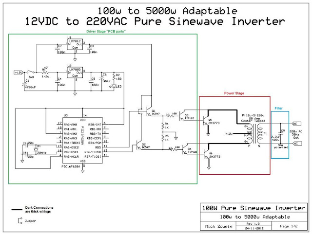
Here is a circuit diagram of 1000w modified sine wave inverter. 1000 watts inverter using two pulse transformer soldering mind.
1000 Watt Pure Sine Wave Inverter Circuit Diagram. Diy cheap 1000w pure sine wave inverter (12v to 110v/220v): The project is based on the low cost egs002 spwm driver board module.
 1000 Watt Pure Sine Wave Inverter (230) PST100S24E From samlexamerica.com
Happy reading 100 w inverter circuit diagram book everyone. Car batteries for powering you home? Replace 15 amp fuse and check for 110 vac at the inverter output wires.
1000 Watt Pure Sine Wave Inverter (230) PST100S24E
Pure sine wave inverters draw power, either from standard 12 volt automobile and marine batteries, or from portable high power 12 volt sources. Make this 1kva 1000 watts pure sine wave inverter circuit homemade projects. Bz 8668 schematics diagrams sine inverter 1000w schematic diagram. 12 volt 1000 watt power inverter design process gohz com.
 Source: powerinverter.org
Sine wave inverter circuit diagram with full explanation. At no instant s1 and s2 should be on simultaneously, if such instants occur it. The home inverter overall structure is, downside is a large cooling plate, upside is a power board with same size as the cooling plate, length 228mm, width. 1cab005 inverter circuit diagrams 1000w wiring library. This modified sine.
 Source: pinterest.com
Power amp 10 000w circuit diagram. The inverter capable to handle loads up to 1000w, it’s depended on your power inverter transformer. Diagram digital schematic 1000w dc ac pure sine wave power inverter circuit. Sine wave inverter circuit diagram with full explanation. If equipped with a 15 amp front panel fuse, check fuse.
 Source: alibaba.com
Make this 1kva 1000 watts pure sine wave inverter circuit. A relatively simple 1000 watt pure sine wave inverter circuit is explained here using a signal amplifier and a power transformer. Pure sine wave inverter converts low voltage, direct current (dc) to 110 volt alternating household current (ac) depending on the model and its rated capacity. 4.2 out of 5.
 Source: gohz.com
Inverters are devices that convert dc input supply to ac (alternating current). Here is a circuit diagram of 1000w modified sine wave inverter. 1000w power inverter circuit simple diagram pure sine wave pdf dc 12v to ac 220v transformer less 12 volt 1000 watt design. Black is the dc input Diagram digital schematic 1000w dc ac pure sine wave power.
 Source: schematics-diagrams.blogspot.com
Is the 15 amp fuse good? Red is the dc input positive pole 2. Here is a circuit diagram of 1000w modified sine wave inverter. 100 watt inverter circuit diagram parts list design tips. Inverter circuit 500w 12v to 220v eleccircuit com.
 Source: samlexamerica.com
As can be seen in the first diagram below, […] Pure sine wave inverters draw power, either from standard 12 volt automobile and marine batteries, or from portable high power 12 volt sources. 500 watts inverter circuit 12 volt to 220 soldering mind. Is the 15 amp fuse good? Make this 1kva 1000 watts pure sine wave inverter circuit homemade.
 Source: stone.umelecforum.ru
Red is the dc input positive pole 2. This is the power inverter circuit based mosfet rfp50n06. Make this 1kva 1000 watts pure sine wave inverter circuit. Red is the dc input positive pole 2. Power amp 10 000w circuit diagram.
 Source: stone.umelecforum.ru
The rfp50n06 fets are rated at 50 amps and 60 volts. 300 watt, 500 watt, 1000 watt, 3000 watt, 5000 watt pure sine wave inverter for sale, 50/60hz output frequency, ac output voltage 110v/220v/230v/240v for option.aug 13, 2021 ·. Td 6992 1000 watt power inverter schematic diagram for reference. 12 volt 1000 watt power inverter design process gohz com. Single.


